Tina2 / Tina2S Anatomy & Repair

Moderator: CrazyIvan

User avatar
CrazyIvan
Posts: 354
Joined: Mon Jul 10, 2023 10:25 am

Re: Tina2 Anatomy & Repair

Post by CrazyIvan »

jannickz wrote: Thu Apr 18, 2024 8:05 am You're absolutely right, my apology.
Who are you apologising for?
jannickz wrote: Thu Apr 18, 2024 8:05 am Visual Inspection: Look for any visible signs of wear, tear, or misalignment on the bearings.
Manual Movement: Try moving the gantry up and down by hand. Does it feel loose or jerky?
Who are you asking?

[Edit: The quoted sections above read very strangely in context... unless "jannickz" and "slybunda" are actually the same person! I had hoped to flush that information out, but perhaps the subsequent silence speaks volumes. However, as the section of my post jannickz quoted includes a website link added by him, it seems there might have been an attempt at advertising.]
 

POSTREACT(ions) SUMMARY


User avatar
CrazyIvan
Posts: 354
Joined: Mon Jul 10, 2023 10:25 am

Shredded / Broken Drive Belt

Post by CrazyIvan »

Just spotted this on my Tina2:
Tina2Anatomy-13-small.jpg
Tina2Anatomy-13-small.jpg (243.09 KiB) Viewed 26 times
Fixed by admin.

It was still working like that, but rather than risk the shred getting caught up I trimmed it off. I will have to look into changing the belt sooner rather than later, I'll report back...
 

POSTREACT(ions) SUMMARY


User avatar
CrazyIvan
Posts: 354
Joined: Mon Jul 10, 2023 10:25 am

Re: Shredded / Broken Drive Belt

Post by CrazyIvan »

Okay, so eventually I was getting mis-registration during the printing of layer 1 (infill was not connecting with the perimeter in some places, and overlapping in others), and if I had not noticed and allowed the print to continue it would have no doubt produced a failed print and spaghetti. I reasoned this was due to the XY motion slipping, and the shredded X belt was a likely candidate (by then it had shredded worse).

Spare Parts

Obviously, before you can replace the belt, you need a new belt. Spares might be available from Entina/Weedo/Weefun, or as standard parts from Amazon/eBay/etc.
  • Tina2/2S X toothed belt: 6mm wide, 370mm long, 2mm pitch, eg "60-S2M-370"
  • Tina2/2S Y toothed belt: 6mm wide, 360mm long, 2mm pitch, eg "60-S2M-360"
I have obtained a small stock of spares suitable for Tina2/Tina2S, so contact me by PM if you would like to buy from me. IMO it is worth having spares on hand for running repairs, rather than delay a project while spares are acquired.

X Belt Replacement

I found it easiest to lay the Tina2 on its back. With the power off, X and Y can easily be moved by hand to aid access to screws etc (it is taken as read that the guard has been removed, for information see post 2 in this thread, first paragraph under heading 'Disassembly').
Tina2Anatomy-14-small.jpg
Tina2Anatomy-14-small.jpg (247.55 KiB) Viewed 25 times
Remove four screws (A) to get the hot-end out of the way, and two screws (B) for the X limit switch. The hot-end and limit switch assemblies can be simply draped over the gantry on their cables, no disconnection required. Note the cable tie securing the X limit switch cable to a pillar; I found this could be slipped off (and slipped back when reassembling).
Tina2Anatomy-15-small.jpg
Tina2Anatomy-15-small.jpg (248.46 KiB) Viewed 25 times
Remove the two tensioner pulleys (C), which slackens the X belt sufficiently to be released from the guide pulleys at each end of the gantry.

[Shredding of the X belt (additional to that in the post above) is visible to the right of the right-hand tensioner pulley. The damage visible on the cooling air duct is where I previously installed a nozzle in the heater block without ensuring the heater block had not twisted in the hot-end, and it was pressing on the plastic duct and melted it.]
Tina2Anatomy-16-small.jpg
Tina2Anatomy-16-small.jpg (245.79 KiB) Viewed 25 times
So far, so good... but now comes the tricky part. The carriage for the hot-end is a plastic part which rides on the X guide rails with linear bearings, and the linear bearings are clipped into the carriage with no obvious means of separation. Rear access is required to get to the belt anchor.

It is unclear what the slots in the carriage molding are for, perhaps some kind of tool to separate the carriage from the bearings. I tried a screwdriver to apply leverage, but the plastic is soft and started to deform so I gave up that idea pretty quickly.

What worked for me was a right-angled pry tool (made of GRP), from a set branded 'Silverline'. Although the photo shows both ends of the carriage separated from the bearings, in fact it is only necessary to disconnect one end (preferably the bottom). When applying leverage, ensure it is to the carriage only and not the linear bearing or guide rail – the rails are hardened steel, but the last thing you need is to bend it.

It requires a bit of courage, but with one bearing released, the carriage and remaining bearing, plus the guide rail, can be removed from the gantry (the guide rails slot into the gantry metalwork at each end, and are only held in place by the carriage).

[Tina2S: the gantry is injection-molded plastic rather than folded steel, and the X guide rails appear to be snapped in rather than slotted in, so I do not recommend trying to remove them. With the hot-end disassembled from the duct/carriage, unsnapping the lower linear bearing allows the carriage to be flipped up, and than is sufficient access to replace the drive belt.]
Tina2Anatomy-17-small.jpg
Tina2Anatomy-17-small.jpg (247.02 KiB) Viewed 25 times
Now the old belt can be removed and a new one fitted. The belt is a press fit into the toothed slot in the carriage. Ensure you are replacing like with like (370mm circumference), and that the teeth are on the inside (I got that bit wrong first go, and had to disassemble again to correct it – so take care and check twice!). Ensure the belt is fully home in the slot, the top should be flush.

With an unusual freedom of access at this stage, it would be silly not to take the opportunity to perform some general maintenance. Using a lint-free cloth, clean any old grease off the guide rails, and then apply a small dab of fresh silicone grease – preferably including the Y rails, Z rails, and Z lead screw.

Re-assemble, using the photos above as a reference:
  1. Re-fit the carriage + bearing + guide rail into the gantry;
  2. Ensure the belt is under the carriage, and the carriage is aligned directly over the remaining bearing (if the carriage is misaligned, it won't fit flat on the bearings – check!), and press home to clip it into place;
  3. Fit the belt around the guide pulleys at each end of the gantry;
  4. Ensure the belt passes under the X motor pulley (see photos above) and re-fit the tensioner pulleys (see note below);
  5. Anchor the X limit switch cable to the mounting pillar (using the existing cable tie or a new one), and re-fit the X limit switch ensuring the correct orientation (two screws);
  6. Re-fit the hot-end (four screws).
Note there seems to be no way to adjust the X belt tension, it is what it is. [Tina2S: the X motor is secured in slotted holes, so X belt tension can be adjusted the same as the Y belt (see below).]

Note: Tensioner Pulleys

Each tensioner pulley comprises two flanged bearings and a spring washer, mounted on a machine screw. The spring washer is fitted between the flanged bearings, as per the photo below:
Tina2Anatomy-18-small.jpg
Tina2Anatomy-18-small.jpg (245.43 KiB) Viewed 25 times
Fixed by admin

This arrangement results in the width between the flanges varying according to how tightly the screw is done up. This could be at least partially responsible for the belt shredding I have experienced.

Y Belt Replacement

Access is much easier than for X belt replacement, with everything accessible from the underside of the Tina2/Tina2S.
  1. Slacken off the Y belt tension by loosening the screws securing the Y motor (access from above, slide the bed to the front of the printer to gain access);
  2. Release the Y belt from the motor pulley and the guide pulley at each end of the Y axis, it may be necessary to remove the guide pulley;
  3. Remove the Y belt from its anchor points on the bed bracket;
  4. Fit the new Y belt (360mm circumference), just zig-zagged around the bracket through the slots;
  5. Fit the Y belt over the motor pulley and guide pulley (or re-fit the guide pulley if removed previously);
  6. Tension the Y belt by sliding the motor, and tighten the screws securing the motor – presumably a similar tension to the X belt is appropriate.
 

POSTREACT(ions) SUMMARY


User avatar
CrazyIvan
Posts: 354
Joined: Mon Jul 10, 2023 10:25 am

Tina2 / Tina2S Nozzles

Post by CrazyIvan »


Left: Nozzle as supplied with (my) Tina2

Centre: Nozzle as supplied with Tina2S

Right: Creality Mk8 nozzle
Tina2Anatomy-19-small.jpg
Tina2Anatomy-19-small.jpg (235.77 KiB) Viewed 24 times
Fixed by admin.

What's the difference? Not a lot. They're all the same length of thread and length overall (near enough), they're all M6x1 thread, they've all got "0.4" stamped on them (not visible in the photo) as the hole diameter (in mm). The only significant difference is that the Tina2 nozzle is 8mm A/F (across flats) and supplied with an 8mm wrench, whereas the Tina2S (and Mk8) nozzle is 6mm A/F and supplied with a 6mm wrench in the tool kit.

It would not surprise me if later models of Tina2 came fitted with the 6mm A/F nozzles.

So the long and the short of it is you can buy Creality Mk8 (and other compatible) nozzles to use in the Tina2S, and I see no logical reason they should not also be used in the Tina2 (but you'll need a 6mm wrench). If anything, it looks to me like the Creality nozzle is finished better, which may mean the internal bores are also more polished than the standard nozzles.


Brass vs. Hardened Steel vs. Silicon Carbide

There is plenty of buzz in the FDM discussion groups that brass nozzles wear out too quickly.
  • Brass: Easily manufactured, therefore inexpensive.
  • Hardened Steel: More demanding to manufacture so mid-priced; won't wear as fast as brass; lower thermal conductivity than brass so can't print as fast.
  • Silicon Carbide: Very expensive; very hard; similar thermal conductivity as brass.
To be clear: wear is an issue with filled filaments such as carbon fibre, NOT the PLA and TPU we use on Tina2/2S. We can print many kg of PLA before there is any significant wear on a brass nozzle, and then replace the nozzle many times over for the cost of one hardened steel nozzle.

And there are significant pitfalls with using anything harder than brass: if you gouge the build plate, it will inflict major damage.
 

POSTREACT(ions) SUMMARY


stratocastom
Posts: 1
Joined: Mon Feb 17, 2025 3:54 pm

Re: Tina2 / Tina2S Anatomy & Repair

Post by stratocastom »

Hi guys,

I've just had what looks to be a fatal issue with my Entina Tina2S - The plastic housing for one of the Y belt tension pins has completely cracked away from the housing.

Has anyone seen (and possibly rectified) this kind of issue? I'm considering drilling a hole through the housing and attempting to fashion a new pin to hold the bearings (although not too hopeful).

Any advice would be greatly appreciated; this has otherwise been a very reliable little printer, so would be sad to see it go.
Tina2Anatomy-20-small.jpg
Tina2Anatomy-20-small.jpg (243.57 KiB) Viewed 23 times
Tina2Anatomy-21.jpeg
Tina2Anatomy-21.jpeg (219.23 KiB) Viewed 23 times
Fixed by admin.
 

POSTREACT(ions) SUMMARY


KenW
Posts: 47
Joined: Fri Sep 08, 2023 10:10 am

Re: Tina2 / Tina2S Anatomy & Repair

Post by KenW »

That's exactly what happened to my Tina2S - see here: https://www.3dprintersforum.co.uk/viewt ... 1584#p1584

Photos of my repair will have to wait a few days, sorry.

I think making a block is not a bad idea (see thread above), but I'm not sure a printed one would be strong enough (and anyway, if that's your only printer you can't print one!). Fitting a block means removing the old mounting to make a smooth surface, and then bolting it down.
 

POSTREACT(ions) SUMMARY


User avatar
CrazyIvan
Posts: 354
Joined: Mon Jul 10, 2023 10:25 am

Re: Tina2 / Tina2S Anatomy & Repair

Post by CrazyIvan »

stratocastom wrote: Mon Feb 17, 2025 4:11 pm Any advice would be greatly appreciated; this has otherwise been a very reliable little printer, so would be sad to see it go.
It seems this might be a common failure, and I see no reason it would not afflict the Tina2 as well as the Tina2S.

With the moulded mounting point relatively intact, as yours is, I would think replacing the threaded insert (take it off the screw first) and then surrounding the area with epoxy should work fine. You just need enough existing material to anchor the epoxy to, and it looks like you have that. Just make sure the top of the insert is level with the moulding and epoxy, and you don't let epoxy get into the insert!

"Plastic Metal" (two-part filler) would be tougher than ordinary two-part epoxy glue. Drilling the plastic with small holes in that area would increase the bond strength. Whatever glue you use, let it harden for a day before trying to fit the pulley and belt.

If the moulding had broken away entirely, I would have suggested getting in there with a Dremel or the like and grinding the area flat, then drilling the deck and putting a new screw through for the pulley to pivot on. The exact position of the pulley is not critical, the motor can be adjusted for tension.

IMPORTANT: This is a good reason not to make the drive belts as tight as possible. Toothed belts don't need to be tight-tight, just tight enough that the teeth can't slip on the toothed capstan on the motor.
 

POSTREACT(ions) SUMMARY


KenW
Posts: 47
Joined: Fri Sep 08, 2023 10:10 am

Re: Tina2 / Tina2S Anatomy & Repair

Post by KenW »

Here is my repair:
Tina2Anatomy-22-small.jpg
Tina2Anatomy-22-small.jpg (241.6 KiB) Viewed 21 times
Fixed by admin.

You can see where I've embedded small screws into the plastic (melted in with a soldering iron) to provide anchoring for the epoxy, and supported the threaded insert with a paper clip.

There is much more surrounding plastic remaining in stratocastom's case, so it should be no problem to rebuild.
 

POSTREACT(ions) SUMMARY


User avatar
CrazyIvan
Posts: 354
Joined: Mon Jul 10, 2023 10:25 am

Re: Bed Heater Fault & Repair

Post by CrazyIvan »

I had long suspected there was something not right with my Tina2S's bed heater. It was not reaching the set temperature at times, and watching the temp on the info screen showed it sometimes going up, sometimes down. I was putting up with that while I still got good prints, but then I had a 4+ hour print I left running overnight ruined by warping and I couldn't tolerate it any longer.

The most likely fault was a broken wire to the heater itself – the sensor was still giving sensible readings. Flexing the cable by hand confirmed that suspicion, the fan changed pitch as the PSU got loaded intermittently.

(Some of the photographs below are cribbed from this post, as I did not keep a photo-journal of this repair.)
Tina2Anatomy-23-small.jpg
Tina2Anatomy-23-small.jpg (246.24 KiB) Viewed 19 times
The wires concerned are within the mesh sheath on the right of the print bed, which passes through the cable duct behind the front right corner of the Tina2S's outer case. It emerges from the duct just below the controller board, and plugs into the controller board with a large 2-pin connector for the power, and a small 2-pin for the sensor. With the printer turned onto its right side, the connectors can be seen (just!), identified, and disconnected: the power plug is obvious with thick red and black wires, the sensor plug is adjacent to it with thin white wires.

IMPORTANT: Tie the end of a couple of feet of string to the power plug before proceeding further. The string will make re-assembly much easier.

While the printer is on its side, release the Y belt from the carriage anchor.

Stand the printer upright again. Now proceed to disassemble the print plate from the Y bearings by removing the 8 screws into the bearing blocks (NOT the two screws securing the belt anchor in the centre of the plate)...
Tina2Anatomy-24-small.jpg
Tina2Anatomy-24-small.jpg (241.95 KiB) Viewed 19 times
...and withdraw the cable. Untie the string from the plug, leaving the string in place through the duct.
Tina2Anatomy-25-small.jpg
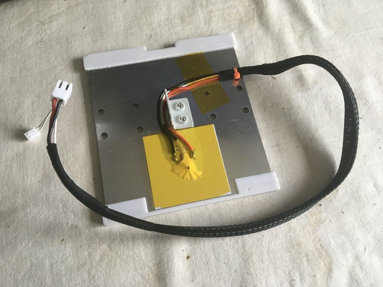
Tina2Anatomy-25-small.jpg (239.45 KiB) Viewed 19 times
Fixed by admin.

NB: the above is a photo of my repaired assembly, not the original one. It also shows my magnetic plate locating fences (the white pieces at opposite ends of the plate) for fine-tuning Y capability.

Be aware of the following:
  • The transparent yellow tape over the heater and securing the cable near the zip tie is high-temperature tape.
  • The sheath will fray at the ends when the heat-shrink tubing is removed.
  • New heat-shrink tubing won't fit over the plugs.
  • The solder joints connecting the power wires to the heater pad are on a huge heat sink, so are all but impossible to unsolder/re-solder (and I didn't want to risk heat damage by cooking the whole lot).
In the event, I found not just one fractured wire but both, with blackening around the break (inside the insulation) very similar to the nozzle heater repair I did previously. The location was where the cable bends back on itself, as seen in the top photo. That point is where the cable flexes repeatedly as the carriage moves in Y, and is necessary to allow the freedom of movement.

The break was obvious: while the rest of the wire was relatively stiff, it was floppy at that point and parted easily when pulled (don't do this yet, see instructions below).

The following is not the exact sequence of operations I used, but that's where you can benefit from my experience of doing this for the first time. These are not proven instructions, particularly details like the pre-shrunk ODs (outside diameters) of heat-shrink tubing. Any feedback welcome.

Before you start, you will need:
  • Replacement wire. It does not matter what colour it is, but red and black wire would be nice. Only need a foot of each, if that (or a couple of feet of one colour). The original wire is 1.75mm OD 16-strand 0.2mm (0.5mm²), so choose something similar (no thinner) and as flexible as possible. It doesn't matter how thick the OD is (within reason), unless you've tuned (or are going to tune) the printer's Y capability as per this thread. Wires taken from a length of 0.5mm² (3A) mains flex will do.
  • Heat-shrink sleeving, fine (pre-shrunk OD 3mm) and medium (OD 10mm).
  • Small zip tie.
  • Sticky tape, eg electricians' PVC insulating tape (specification unimportant).
  • Soldering iron and solder, miscellaneous tools. Note that leaded solder is much easier to work with than lead-free solder!
As previously noted, it would be a pig to replace the wire at the solder connections to the heater, so don't try. Similarly the crimped connection at the connector, so don't. Instead, splice in a length of wire to replace just the section that is broken, with the joints in places which do not suffer flexure.
  1. Carefully peel back the high-temperature tape securing the wires to the plate, sufficient to release the wires. Do this from the front edge of the plate – where the tape passes across a mounting hole it will be more fragile.
  2. Cut the zip tie.
  3. With a sharp craft knife, slit the sleeving at the end of the mesh sleeve (just this end, not the other end) and remove it.
  4. Trying not to let the mesh fray any more than it is already, pull it back to bare the wires as far as possible and temporarily tape it in place (helping to prevent fraying and clearing the working area). Identify the location of the break.
  5. On one wire only: Cut the wire as far up the cable as is comfortable to work with. Strip the top end of the cut wire about ¼". Strip the end of the replacement wire similarly, and solder them together (I like to "merge" the stranded conductors into each other, and they then need taping to a wood block – or something – to solder them... or two pairs of hands). Feed on a 1" length of 3mm heat-shrink to insulate the joint (ideally use a heat gun to shrink it, although a soldering iron will do it). Feed another 1" length of heat-shrink onto the same wire, for later.
  6. Cut the same wire at the plate, next to the belt anchor. Now stretch the cable out straight, right through from the connectors to the heater, so the remaining intact wire is taught. Cut the replacement wire so there is a ¼" overlap with the cut end to the heater.
  7. Now you can cut the other wire next to the heater, at the same position as the first.
  8. Repeat step 5 for the other wire.
  9. Cut the replacement wire to the same length as the first.
  10. Feed a 1½" length of 10mm heat-shrink over both wires together.
  11. Strip the ends and solder, make sure the heat-shrink is as far away from the soldering as possible.
  12. Slide the 3mm heat-shrink down to cover the joints, and shrink. Slide the 10mm down to cover both joints, and shrink.
  13. Remove the crimp terminals from the power connector. This can be done using a fine screwdriver to depress the metal latches, and then the terminal slides out of the housing easily.
  14. Feed the sensor plug through a 1½" length of 10mm heat-shrink, then the power crimps. Slide the heat-shrink over the top end of the mesh sheath, then remove the tape securing the bottom end. Stretch the sheath down over the repair to the edge of the plate, and slide the heat-shrink down to just cover the end of the sheath. Shrink the tube to secure everything.
  15. Check the correct orientation from the photos, and re-fit the crimp terminals into the connector housing (it probably doesn't actually matter which way around they are, but...). If the latches don't hold, having depressed them it may be necessary to tease them out again so they latch properly.
  16. Secure the cable to the plate with a zip tie, as per photos. If you have tuned your Y motion, take care to ensure the tie (and the thickness of the cable at that point) won't foul the chassis.
  17. Replace the high-temperature tape.
To re-assemble the printer, tie the string added previously to the power plug, and use it to tease the cable through the cable duct. Plug in the connectors (fiddly!).

Assemble the bearing blocks, position the print plate over them, and refit the screws. Under the printer, re-secure the Y belt to the anchor.

Check the plate moves freely to both ends in Y. It should reach the back end-stop (the microswitch should click) before the bed heater cable fouls the Z motor coupling. At the front end-of-travel, f the Y tuning has been performed, the cable under the build plate should clear the lip of the chassis.

If the Y motion can't trigger the end-stop microswitch, the printer will report a Y error when it tries to home the nozzle.

NB: With the disassembly required to repair the bed heater cable, it would be an excellent opportunity to perform some of the Y tuning modifications at the same time – see HERE.
 

POSTREACT(ions) SUMMARY


Post Reply